
Plotting and cutting
The Plot button in the top bar sends a design to a vinyl cutter or pen plotter, or writes the job to a file for another program to send. Everything about the job (the command language, the axes, force, speed, which head holds the blade) belongs to the machine you choose, so the first step is to add the machine you own. After that, a plain cut is: open Plot, check the preview, pick how the machine is connected, press Cut.
Opening the Plotter dialog
Click Plot in the top bar (tooltip: Send the design to the cutter). The Plotter dialog opens with two tabs:
- Output holds everything about this job. The controls run down the left: the machine, the canvas toolpath preview, file export, end-of-job behavior, print-and-cut, and the Connection the job is sent over. The right column is the Cut preview, a picture of how the job will land on the machine.
- Plotter defaults holds the tuning saved against the machine: units, scale, rotation, feed, tolerance, heads, force, speed, passes and blade.
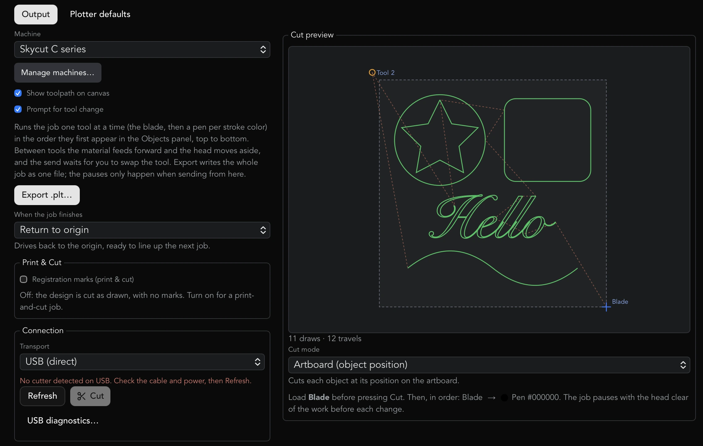
Opening the dialog changes nothing in the document. One setting on the Output tab does belong to the document: the Registration marks (print & cut) checkbox under Print & Cut. It is saved in the .lf file, so a print-and-cut sheet opens as one.
Adding your machine
Both tabs start with a Machine dropdown. Until a machine is added it reads No machines added, and the dialog asks you to add the cutter or plotter you own.
Press Manage machines… to open the Machines dialog. Your machines at the top lists what you have added, each with a Remove button. Under Add a machine, pick the brand first, then the model: the brand list shows how many models each has, and choosing one shows its models with Add next to each. ‹ All brands goes back. Each model shows whether it is Confirmed or Not yet confirmed on hardware, and says print & cut if it has a registration camera. If you know the name, type it in Search brands and models… and the matching models are listed directly, whatever brand they belong to. Press Done when finished.
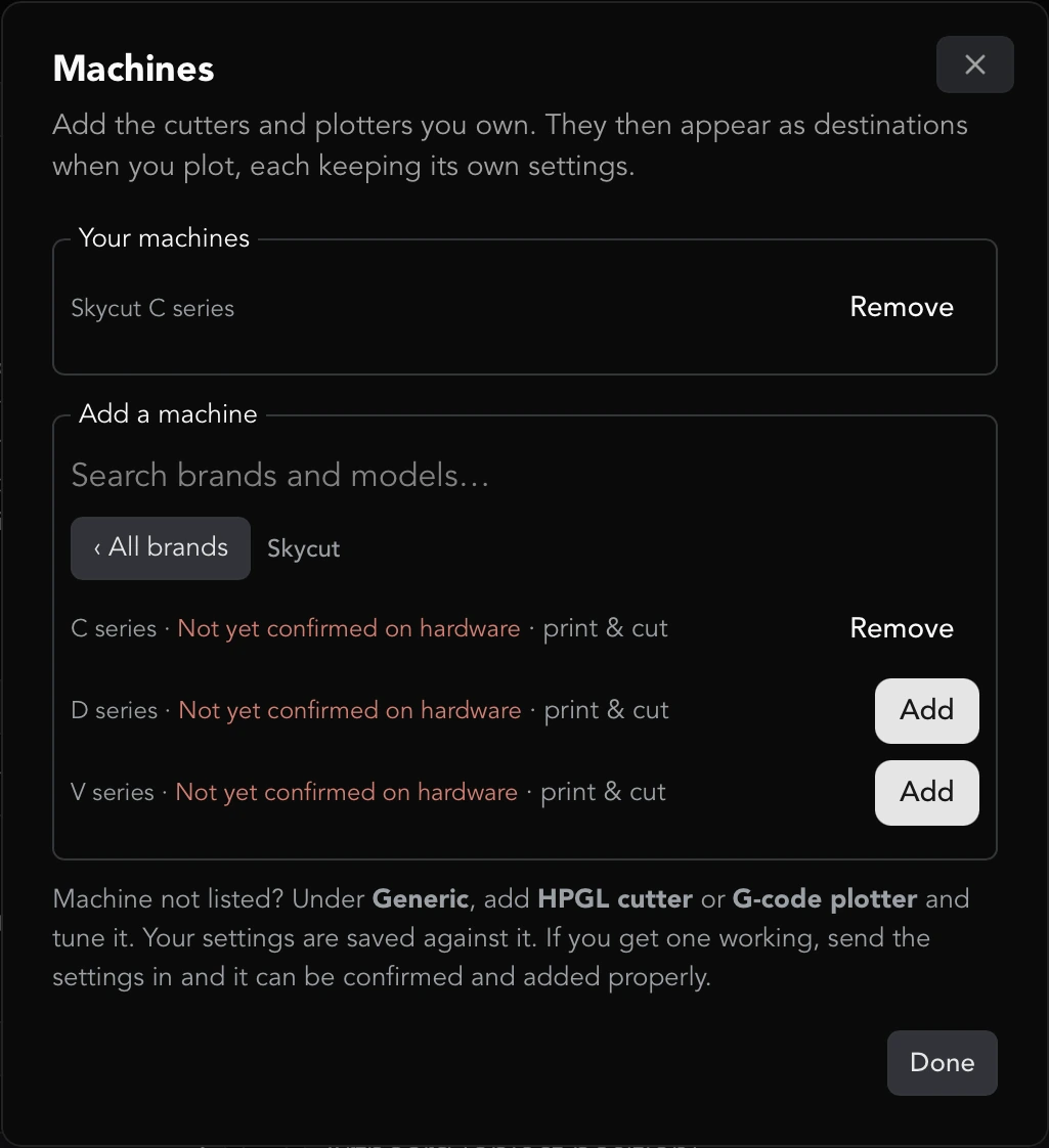
Each machine keeps its own settings, so a Skycut and a pen plotter never share one set of numbers, and the right axes and units are set the moment you add one. Settings made before machines existed are carried over automatically as a machine.
If a supported cutter is plugged in over USB and recognized by its USB ids, a button such as Add Skycut C series appears next to Manage machines… so you can add it in one click. Some cutters are sold under more than one name (a Skycut C16 is also the Starcraft SOLO and the Siser Romeo and Juliet) and answer identically when asked what they are, so for those no one-click button appears until you have chosen; the device line names them all and you pick yours under Machine or Manage machines…. Once chosen, the cutter is always listed by the name you chose.
If your machine is not listed, open the Generic brand and add HPGL cutter or G-code plotter, then tune it; the settings are saved against it. If you get an unlisted machine working, send the settings in so it can be confirmed and added properly.
The toolpath preview
On the Output tab, check Show toolpath on canvas to draw the planned job over the artwork on the canvas. Cut runs are drawn in green, draw (pen) runs in blue, and pen-up travels as dashed orange lines. Objects set to Ignore are absent. The preview refreshes as you edit the document or change settings.
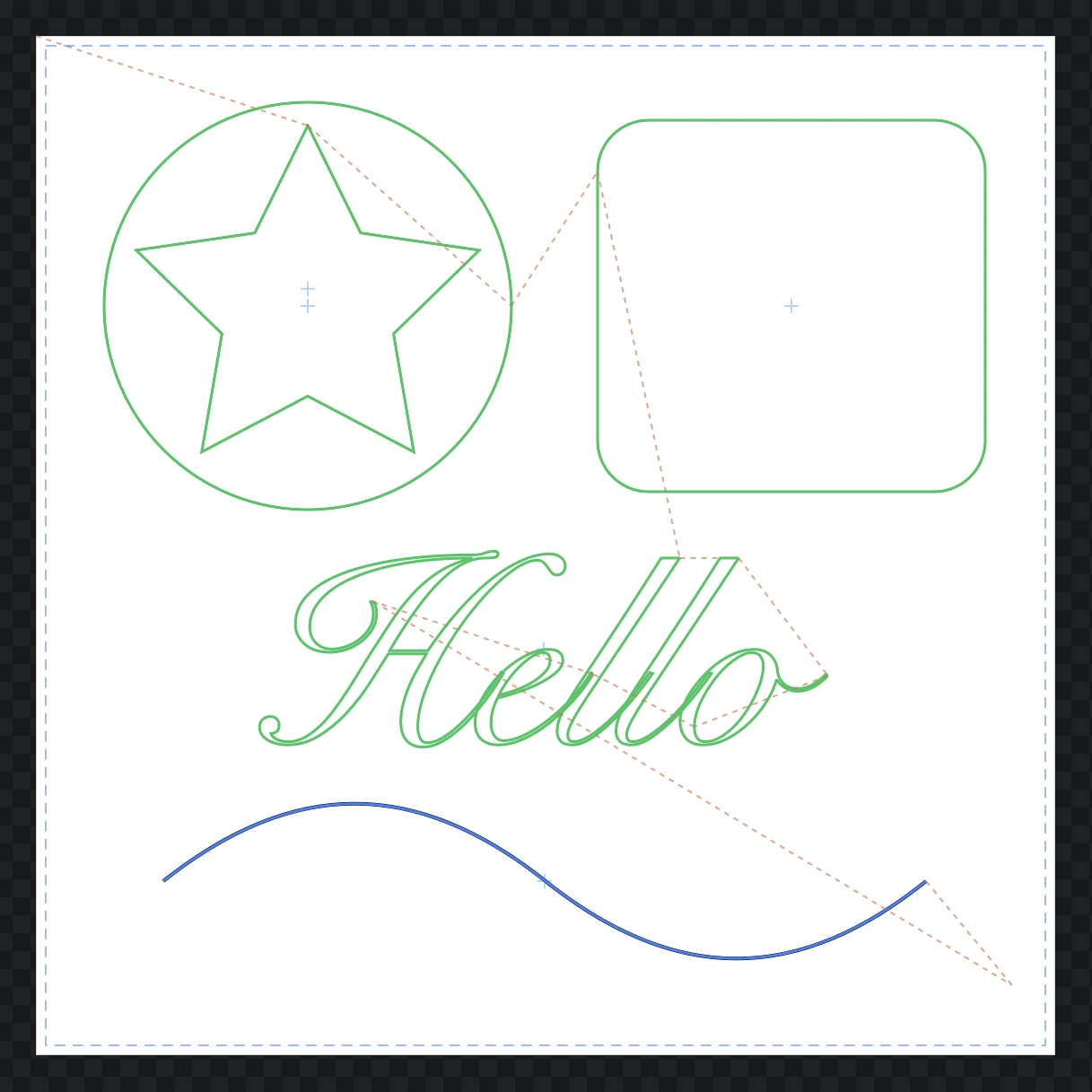
The canvas preview shows the job in document space. Machine rotation, flip and cut mode only apply to the output; the Cut preview beside the controls shows those (see The Cut preview).
Exporting a job to a file
Press Export G-code… or Export .plt… on the Output tab to write the job to a file instead of sending it. Which one you see depends on the machine: a G-code machine writes a .gcode file, and an HPGL machine writes a .plt file in that machine's dialect. There is no separate format picker; choosing the machine settles the language, so a Skycut cannot be handed generic HPGL by mistake.
The file is the complete job, with every setting from both tabs applied (units, scale, rotation, flip, force, speed, passes, blade compensation, end-of-job move). A job planned with Prompt for tool change is written as one continuous file; the pauses only happen when sending from the app.
When the job finishes
Machines whose language includes a move back to the origin (the Skycut C, D and V series) show When the job finishes on the Output tab:
- Return to origin drives back to the start point, ready to line the next job up. This is the default.
- Stay where it finished lifts the blade and stops at the last cut.
- Advance clear of the job lifts and moves past the finished work, so roll material can be taken off without the carriage sitting on it.
The blade is lifted in all three; only where the head then goes changes. The setting is kept per machine. On Generic HPGL and G-code machines there is nothing to choose, so the control is not shown.
Plotter defaults: axes, units and scale
The Plotter defaults tab holds the machine's tuning. The left column:
- Rotate turns the output a quarter turn at a time: None, 90° CW, 180° or 270° CW. Use it when the machine's axes run across the canvas rather than along it. Every Skycut profile starts on 90° CW.
- Units is mm or inch, the unit the job is written in.
- Scale multiplies the output. 1 is life size.
- Feed rate is the pen-down cutting speed for G-code machines, in machine units per minute. HPGL machines use Cut speed instead.
- Tolerance is how closely curves are followed, in document units. Smaller is more accurate and produces more points; the default is 0.1.
- Flip Y (screen → plotter) flips the vertical axis. The screen is Y-down and most plotters are Y-up, so this starts on.
- Flip X (mirror left ↔ right) mirrors the job across the page's vertical axis before it is rotated. It is for a machine whose carriage runs the other way from its relatives, so the origin is on the left rather than the right: the Siser Romeo and Juliet start with it on, every other machine off. With it on, the Cut preview shows the origin at the bottom left and an arrow drawn pointing left cuts pointing left; with it off on one of those machines, the cut comes out mirrored.
- Optimize travel order reorders the paths so the head takes the shortest pen-up trips between them (nearest neighbor). With Prompt for tool change on, the reordering happens within each tool rather than across the whole job, so tools are never interleaved.
Plotter defaults: heads
On a machine that declares more than one carriage (the Skycut D series) the right column has a Heads section:
- Cut with is the carriage that holds the blade.
- Draw with is the carriage that holds the pen.
Set them once to match what is loaded on the bench. The profile guesses blade on the left and pen on the right, and the machine cannot tell the app which is true, so put pens in both heads and run a test job before loading a blade. An object's own head choice (right-click → Plot settings…) still overrides these.
Plotter defaults: force, speed, passes
- Force is the blade pressure. Blank (Machine default) leaves the machine's own panel value alone.
- Cut speed is the speed while cutting. Blank leaves the machine's value alone.
- Up speed (HPGL machines only) is how fast the head moves with the pen up, so a slow, controlled cut need not mean a slow job. Blank means Same as cut speed. It is sent before each travel and the cut speed is sent again before each cut, and it is only sent at all when there is a cut speed to come back to: with Cut speed blank the dialog says so and the machine's own speed is left alone throughout. G-code rapids already run at the controller's maximum, so the control is not shown for them.
- Passes cuts every outline this many times, 1 to 10, for material too dense or thick to get through in one go.
When the machine declares a range, the label shows it (Force (1–160) and Cut speed (1–13) on a Skycut) and a value outside it is brought back in when you leave the field, including a value saved for a different machine. Generic HPGL and G-code machines accept any number, because plotters do not share a scale.
These are defaults for every object; an object can override them (see Cut versus draw below).
Plotter defaults: blade
The Blade section compensates for the blade's swivel:
- Material fills the two fields from a preset: Pen (no blade) (0 / 0), Standard blade (45°) (0.3 mm offset, 1.0 mm overcut), Thick material (60°) (0.5 mm offset, 1.0 mm overcut). It reads Custom when the values match no preset.
- Blade offset (mm) is the distance from the blade's pivot to its tip. Corners are rounded by this radius in the output so the blade swings round them cleanly.
- Overcut (mm) cuts a little past the start of each closed shape so the final corner cuts through.
Because LineaForge compensates here, set the machine's own blade-offset setting to 0. Blade compensation applies to objects set to Cut (blade) only; drawn objects are never offset or overcut.
Cut versus draw: how objects map to blade and pen
Every object has a plot role. Right-click an object on the canvas and choose Plot settings… (or click the plot badge next to it in the Objects panel) to open the Plot settings dialog:
- Role is Cut (blade), Draw (pen) or Ignore. Cuts get blade offset and overcut; draws do not; ignored objects are left out of the job. New objects are cuts.
- Head appears only on a two-head machine: Automatic (by role) sends cuts to the blade head and drawn work to the pen head; naming a carriage sends the object there without changing its role, so a cut stays a cut, blade offset and all, wherever you run it. This is what makes two blades usable.
- Force, Cut speed and Passes override the plotter defaults for this object. Blank uses the default. A value outside the machine's range is refused with a message rather than silently changed.
Reset to defaults clears the overrides; Apply saves them. Selecting a group applies the settings to every member. The Objects panel shows a badge on any object whose plot settings differ from the default.
A line fill has its own role. In the Inspector's fill settings, Plot with is Draw (pen), Cut (blade) or Skip when plotting, with its own Head on a two-head machine, so one shape can be cut round the edge on one head and drawn inside on the other.
On a single-head machine the role still decides blade compensation, but every object runs on the one carriage with whatever tool is loaded. To run a mixed job on such a machine, use Prompt for tool change.
Prompt for tool change
On a machine with one head, the Output tab has a Prompt for tool change checkbox. It runs the job one tool at a time: every cut object is the blade, and every drawn object is a pen in its stroke color (the fill color when it has no stroke; black when it has neither), so a design with black and red lines and a cut outline is three tools. A line fill is its own pen in its own color.
The tools come in the order they first appear reading the Objects panel from the top, and the objects within each tool keep that order too. The Cut preview lists them (Load Blade before pressing Cut. Then, in order: …) and marks where the head will park for each change.
Between tools the material feeds forward and the head moves aside, clear of the design, and the Change tool dialog appears: Part 1 of 3 is done. The head has moved clear of the work. Load Pen #ff0000, then press Continue.
- Continue sends the next part.
- Stop job ends the job cleanly from the park point, lifting the pen and honoring the end-of-job setting. The status then reports which tools were not run.
The dialog cannot be dismissed any other way, because the machine is mid-job while it is up. Do not move the material or set a new origin between tools: the machine sees one continuous job throughout, so the rest of it is positioned from where it started. A design drawn in six colors with one pen will prompt six times; make the objects one color to avoid that.
The setting is kept per machine, and is not offered on a two-head machine, which changes tools by switching carriage instead.
Tool-change prompting and up speed have not yet been run on a machine. Try them with pens in every tool first.
Sending a job: choosing a transport
The Connection section on the Output tab has a Transport dropdown with four choices. The choice is remembered per machine, so a cutter on the network and a plotter on a COM port each keep their own, and a machine you have never chosen for starts on the transport its profile prefers.
- USB (direct) for a cutter on a USB cable. Preferred by the Skycuts.
- Serial / COM port for plotters that present a serial port, including GRBL controllers. Preferred by the generic machines.
- Printer/driver queue for a cutter installed as a printer that accepts its language through the print spooler.
- Wi-Fi (network) for a cutter with its own network connection, such as a Skycut.
Every transport has its own Cut button, which sends the job. Whichever transport you use, the job sent is identical to the file Export would write.
Sending over USB
With USB (direct) selected, the panel says what it sees:
- Cutter connected: … names the one attached cutter by its USB ids (and its model string, when the machine reports one).
- No cutter detected on USB. Check the cable and power, then Refresh. when nothing is found.
- With more than one cutter attached, a Which cutter (N attached) picker appears, labeled by USB ids, which is what tells two machines on the same bus apart.
Press Refresh after plugging a machine in. Press Cut to send.
Skycuts C, D and V all present the same USB identity, so LineaForge asks the machine what it is, the same query the manufacturer's software uses, and lists it by the model it reports. A model this build does not recognize yet is shown next to the cutter rather than mislabeled, with a request to send the string in.
On Windows, a Skycut presents itself as a USB printer-class device, which Windows hands exclusively to its own built-in driver. LineaForge connects through that printer-class interface first, the same way the manufacturer's software does, so nothing needs installing: no driver, no Zadig, no administrator rights, and your existing Skycut software is unaffected. A cutter running some other manufacturer's driver can be seen but not opened; for those, use Printer/driver queue or Serial / COM port. On macOS there is no such gate.
Sending over a serial or COM port
With Serial / COM port selected:
- Port lists the serial ports on the system, with a description where the system gives one. Press Refresh after plugging in.
- Baud is the port speed: 9600, 19200, 38400, 57600, 115200 or 250000. Generic HPGL defaults to 9600 and GRBL to 115200.
- GRBL: wait for “ok” after each line appears for G-code machines. Leave it on for a GRBL controller: the job is streamed one line at a time and each line waits for the controller's acknowledgement, which is the flow control GRBL expects.
Press Cut. An HPGL job is written as one stream of bytes; a G-code job is streamed line by line, and the status reports Streamed N lines to ….
The port and baud are not yet remembered between sessions.
Sending over Wi-Fi
With Wi-Fi (network) selected:
- Cutter IP address is the address the cutter shows for its own Wi-Fi.
- Port is filled in from the machine profile: Skycuts listen on 8080.
Press Test connection before sending anything. It connects and asks the cutter what it is: a Skycut answers with its model, and the result says whether that model is one this build recognizes. A machine that connects but does not answer the model query is fine; the address is right.
Press Cut to send. This is a plain network connection, the same one the Skycut software uses, so it behaves identically on Windows and macOS and none of the USB driver questions apply. The address and port are remembered with the machine.
The Wi-Fi transport has not yet been confirmed against hardware; if it fails, Test connection says what happened.
Sending to a printer or driver queue
With Printer/driver queue selected, Queue lists the printer queues on the system. Press Refresh to rescan and Cut to spool the job as raw bytes. This is for a cutter installed as a Windows printer that accepts HPGL through the spooler, and is usually the transport that works on Windows when direct USB cannot reach a machine running its manufacturer's driver. The queue is not yet remembered between sessions.
The Cut preview
The Cut preview fills the right column of the Output tab, whichever transport is selected. It draws the job as it will physically cut, relative to the blade's start point, which is marked with a crosshair labeled Blade. Travels are drawn as well as cuts, the artboard outline is shown in Artboard mode, and on a tool-by-tool job the park points are marked Tool 2, Tool 3 and so on, so you can see the head will wait off the work. Blade compensation is left out of the preview so positioning reads cleanly. The machine's rotation and flip are undone for the drawing, so what you see is what you will get on the bed.
Cut mode decides where the job lands:
- Artboard (object position) cuts each object at its position on the artboard, with the blade's start point as the artboard's origin.
- Blade point (start at the blade) ignores object position; the cut starts at the blade's current point.
- Center (on the blade point) centers the whole job on the blade's current point.
Under the drawing, the preview reports the count of draws and travels. Extra passes are included, so a job set to three passes shows three times the draws. On a tool-by-tool job it also says what to load first and lists the order. Sending happens under Connection on the left.
What the success message reports
After a send, the result appears under Connection on the Output tab, because a job that sent perfectly and one that never left must not look the same:
- Over USB: Sent N bytes over USB (printer-class interface). or Sent N bytes over USB (libusb, interface 0, bulk endpoint 0x02). The route and endpoint are the first thing to quote in a report.
- Over serial: Sent N bytes to COM3. for HPGL, or Streamed N lines to COM3. for G-code.
- Over Wi-Fi: Sent N bytes over Wi-Fi to 192.168.27.200:8080.
- To a queue: Sent N bytes to … followed by the queue name.
- A tool-by-tool job: Sent all 3 parts, N bytes in total, …, or Stopped after part 1 of 3. The job was ended cleanly … if you pressed Stop job.
If the message says the job was sent and the machine did not move, it received the bytes and ignored them, which is a different problem from a failed send. A failed send shows an error instead, naming what actually happened and the underlying error.
USB diagnostics
USB diagnostics… appears under the USB transport. It opens and claims each attached cutter for real, releases it, and prints what happened, so it distinguishes the three cases that look identical from the panel: no machine found, a machine found that the system will not let the app drive, and a machine that takes the job and ignores it. It also prints the model string the machine reports. The text is copied to the clipboard; paste it into a bug report.
It is a button rather than automatic because claiming an interface is exactly what must not happen behind your back mid-job.
Print-and-cut: cutting a printed sheet
The Print & Cut section on the Output tab holds everything about a print-and-cut job. Tick Registration marks (print & cut) to turn the document into one: the marks appear on the artboard at once, print with the sheet, and tell the cutter where the printed artwork sits. Untick it for a plain cut. The setting is saved with the document. With the marks on, the section shows their settings, each applying immediately:
- Placement: Around objects puts the marks just outside the artwork; Relative to page puts them at a fixed inset from the page edge.
- Mark size: L 20 × 20 mm or L 9 × 9 mm.
- Mark offset (mm): the distance outside the objects, or the inset from the page, depending on the placement.
- Line thickness (mm).
- Origin corner: Bottom-right, Bottom-left, Top-right or Top-left.
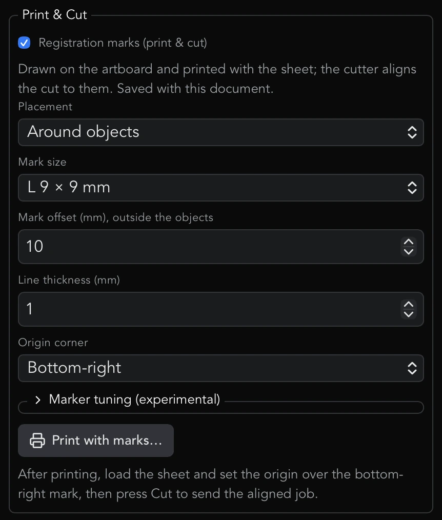
Marker tuning (experimental) is collapsed under the mark settings and holds Cut orientation, Swap width/height order (TB26 / FSIZE) and Working field (FSIZE). The Skycut camera command format is unverified; if a print-and-cut overshoots a mark or comes out rotated, try these, then print and cut again.
If the selected machine has no registration camera, the section says so: the marks still print, but that machine cuts the design as a plain job.
Below the settings, Print with marks… prints the sheet at exact 1:1 with the marks; the Export and print help covers that dialog. The cutter side:
- Load the printed sheet and set the blade origin over the mark named in Origin corner (the lower-right mark by default).
- Press Cut under Connection. For a camera machine the job is sent in marker mode: the cutter scans the four marks, builds its coordinate frame from them, and cuts the contour aligned to the print. The marks themselves are never cut.
- In marker mode the job is planned in the page frame as printed: Rotate and Flip Y from Plotter defaults are ignored and Cut mode is forced to Artboard (object position), because the job is positioned from the printed marks and the camera reconciles the machine's axes from them. Cut orientation under Marker tuning (experimental) in the same section is the knob if the result comes out turned or mirrored.
If the marks would run past the page, the section warns: Marks extend past the page. Reduce the mark offset above or the design size.
Print-and-cut has not been confirmed end to end on any machine. Run it with a pen first and check that the pen traces the printed outline before loading a blade. Only machines whose profile declares a camera (the Skycut C, D and V series) will send a marker job; a Generic HPGL machine never does.
Skycut C series
- Added automatically: it is recognized by its USB ids, and Add Skycut C series appears when one is plugged in.
- Language: the compact Skycut HPGL (
IN;PA;P0;, oneU/Dcommand per point,@;to finish). Transport prefers USB (direct); Wi-Fi on port 8080 is also available. - Defaults: mm, Rotate 90° CW, Flip Y on, Artboard cut mode.
- Force (1–160) and Cut speed (1–13) are held to the machine's own panel range. Up speed is available.
- One head, so Prompt for tool change is offered and there is no Heads section.
- When the job finishes is offered.
- Print-and-cut is available.
Listed as Not yet confirmed on hardware: the header, moves and footer match .plt files the cutter itself produced, but the tool, force and speed commands are inferred from generic HPGL, and the print-and-cut protocol was reverse-engineered on a D-series. No C-series has cut from LineaForge yet. Dry-run with the pen tool first.
Starcraft SOLO
- The Starcraft SOLO is a Skycut C16 under a different badge, and this profile is the Skycut C series profile with the name changed: the same language, transport, defaults, ranges and print-and-cut.
- Added by hand from Manage machines… (brand Starcraft). It carries the Skycut USB identity and answers the model query as a C16, so a plugged-in SOLO cannot be told from a Skycut C by the app alone: with no machine chosen, the device line says it identifies as a Skycut C series and names the SOLO among the machines it is also sold as. Once Starcraft SOLO is selected under Machine, the cutter is listed as a Starcraft SOLO everywhere. Either machine produces the identical job.
- Everything in the Skycut C series section above applies, including Not yet confirmed on hardware. No SOLO has cut from LineaForge. Dry-run with the pen tool first.
Siser Romeo and Siser Juliet
- Siser's 24" (Romeo) and 12" (Juliet) cutters, driven from Leonardo Design Studio. Under the badge each is a Skycut C series machine: the same language, transport, defaults, ranges and print-and-cut, and everything in the Skycut C series section applies.
- The one difference: Siser turned the carriage axis around so the origin sits at the bottom left of the machine rather than the right. A job written with the Skycut C settings cuts mirrored on them, so these two profiles start with Flip X (mirror left ↔ right) on and the Cut preview shows the origin at the bottom left. Leave it on; an arrow drawn pointing left then cuts pointing left.
- Added by hand from Manage machines… (brand Siser). Once selected under Machine, the cutter is listed as a Siser Romeo or Siser Juliet everywhere: the device line and the Wi-Fi connection test never call it a Skycut. With no machine chosen, a plugged-in Siser is assumed to answer as the C16 it is built on, and the device line names the Romeo and Juliet among the machines that cutter is sold as. Whether a Romeo or Juliet really presents the Skycut USB identity and answers the model query that way is not yet known; if USB diagnostics… shows something else, please send it in. Print-and-cut on these machines is planned in the page frame as printed, where Flip X is ignored like Rotate and Flip Y; if a print-and-cut comes out mirrored, Cut orientation under Marker tuning is the setting to change.
- Listed as Not yet confirmed on hardware: no Romeo or Juliet has cut from LineaForge. Dry-run with the pen tool first.
Skycut D series
- Added by hand from Manage machines…. It shares the C-series USB ids, so until its model string is known it is announced as a C in the USB device line; that is cosmetic, because the job is written for the machine selected under Machine. If USB diagnostics… shows the model string, please send it in.
- Language: byte-for-byte the C-series dialect, confirmed against a file produced for a D-series.
- Two heads, Left and Right. Cuts go to the Cut with head and drawn work to the Draw with head (Plotter defaults → Heads), with left-blade, right-pen as the starting assumption. The machine cannot report what is loaded, so put pens in both heads for the first job.
- Same ranges as the C series: Force (1–160), Cut speed (1–13). When the job finishes and Up speed are offered. Prompt for tool change is not, because a two-head machine changes tools by switching carriage.
- Print-and-cut is available, and this is the machine the marker protocol was taken from.
A simple shape has been cut on a D-series from LineaForge over the USB printer-class connection. The force and speed commands remain inferred, and print-and-cut on it is unconfirmed.
Skycut V series
- Added by hand from Manage machines….
- The D-series dialect on a single-head machine. No head-select command is ever sent, so an object marked Draw (pen) runs on the same carriage as a cut, with whatever tool is loaded; blade offset and overcut still follow the role. Use Prompt for tool change for a mixed job.
- Same ranges and options as the C series, including When the job finishes and Up speed.
- Print-and-cut is declared on the assumption that the V carries the same camera as the D.
Listed as Not yet confirmed on hardware: no V has been run from LineaForge. Check with a pen before loading a blade.
GRBL and G-code plotters
Add Generic G-code plotter. It writes standard GRBL-style G-code: G21 or G20 for the unit, G0 rapids for pen-up travels, G1 at Feed rate for pen-down moves, and Z-axis moves to lift and lower the pen (up at Z5, down at Z0). Per-object Cut speed overrides are written as feed words on those moves.
- Transport prefers Serial / COM port at 115200 baud, streamed line by line with GRBL: wait for “ok” after each line on.
- Defaults: mm, no rotation, Flip Y on, Artboard cut mode.
- Force has no meaning in G-code; Feed rate is the speed that matters. Up speed is not offered because
G0already runs at the controller's maximum. When the job finishes is not offered. - No ranges are enforced, and no print-and-cut.
The profile is standard G-code rather than any one machine, so it carries no hardware verification note.
Generic HPGL cutters
Add Generic HPGL cutter for any machine that speaks standard HPGL but has no profile of its own. It writes IN;SP1; to start, PU x,y; and batched PD polylines, SP1; for cuts and SP2; for draws, FS for force and VS for speed, and PU; to finish.
- Transport prefers Serial / COM port at 9600 baud; the other transports can be selected if that is how the machine is reached.
- Defaults: mm, no rotation, Flip Y on, Artboard cut mode.
- Force and Cut speed accept any number: this profile stands in for every plotter and they do not share a scale. Up speed is offered.
- No When the job finishes choice (the job always ends with a pen lift), and no print-and-cut: a marker job must never be sent to a machine without a camera.
Tune it until your machine behaves, then send the settings in so the machine can be confirmed and added properly.
What has not been verified on hardware
The command languages are checked against files captured from the machines, but several features have not yet been run on a real machine. Use the pen tool before a blade for any of these:
- Skycut C series and V series: no cut yet from LineaForge. The D series has cut a simple shape over USB.
- Print-and-cut on any machine, including the Skycut camera command format and the Marker tuning defaults.
- Prompt for tool change and Up speed: whether the head parks beside the work rather than on it, whether the second tool lands where the preview says, and whether the up speed actually speeds up travels. The Wi-Fi and printer-queue transports open a new connection or spool job per part, which has not been tested either.
- Passes (multi-cut): the toolpath is tested, but whether lifting and re-plunging at the start of each pass is what a real blade wants on thick material is not.
- Wi-Fi (network) has not been run against hardware.
- The inferred force and speed commands on all three Skycuts.
Anything you can confirm, along with the status line shown under Connection after a send and the output of USB diagnostics…, is the most useful thing to send in.