
Export and print
LineaForge writes your design out in two ways. The File → Export menu turns it into a file another program can open: a vector file for a cutter, a layout program or a 3D printer, or a picture for the web. The Print button sends it to a printer, with a preview that shows the real sheet, the real printable area and exactly where the artwork will land. Print-and-cut combines the two: you print the sheet with registration marks, then the cutter's camera reads those marks and cuts around what you printed.
Choosing what an export covers
Every format under File → Export follows the scope set at the top of that menu:
- Whole artboard exports the entire page. This is the default.
- Selection only exports just the objects you have selected, cropped to them. The page becomes their size, everything else on the artboard is left out, and the artboard background is not carried over, so the result drops onto whatever you place it on. Room is left for strokes and shadows so nothing is shaved off the edge.
Selection only is grayed out until something is selected, and if you clear the selection the export falls back to the whole artboard. Picking a scope keeps the menu open, so choosing the scope and the format is one trip.
Every export asks where to save. If the file picker leaves the extension off, LineaForge adds the right one.
Which format to choose
- Sending the design to another cutter program (SignMaster, Silhouette Studio, Sure Cuts A Lot, Inkscape, a CNC or laser program): SVG if the program reads it, since it keeps curves and colors; DXF if the program wants CAD files or does not read SVG well.
- Cutting or plotting directly from LineaForge: no export is needed. Use the Plot button; see the Plotting and cutting help. Export G-code… and Export .plt… in that dialog write a machine job file, which is different from the design files here.
- A proof or a file for a print shop: PDF.
- Placing the drawing in a page-layout or desktop-publishing program: PDF or EPS, bearing in mind EPS drops opacity.
- A picture for a web page, a message or a document: PNG for transparency, JPEG for a photo-like image with the smallest file, WebP for both.
- A website's icons: Favicon set….
- A 3D print or a relief: STL (3D)….
What each format carries from the canvas:
- Opacity: SVG, PDF, PNG, WebP and JPEG (flattened onto the background) keep it. EPS, DXF and STL do not.
- Embedded images: SVG and the picture formats keep them. PDF and EPS skip them. DXF and STL have no images.
- Curves: SVG, PDF and EPS keep true curves. DXF flattens them to short straight segments. STL is a triangle mesh.
- Colors: all except DXF (no colors or layers are written) and STL (a mesh has no color).
- Effects such as line fills, shadows, extrusions and variable-width strokes: rendered into every format, as they look on the canvas.
SVG export
File → Export → SVG… writes a standard SVG. It is the most complete format: fills, strokes, opacity, embedded images, cropped images and their outlines, shadows, extrusions, line fills and variable-width strokes all come through as they look on the canvas. Use it to move work to another design program, to a web page, or to cutting software that reads SVG.
PDF export
File → Export → PDF… writes a single-page vector PDF. Paths are written as true vector paths with fill and stroke, a variable-width stroke becomes a filled band in its stroke color, and opacity is carried. Embedded images are skipped. Good for sending a proof, or for layout and print programs that prefer PDF to SVG.
DXF export, for other cutting software
File → Export → DXF… writes an AutoCAD-style DXF (R2000 ASCII). Every object is flattened to a polyline, so curves arrive as many short straight segments, and colors and layers are not written. Choose DXF when the program on the other end is CAD, CAM or a cutter's own software that reads DXF rather than SVG. DXF is Y-up where the document is Y-down; the export flips the drawing by the page height so it opens the right way up.
EPS export
File → Export → EPS… writes Encapsulated PostScript. Paths come through as PostScript paths with fill and stroke, and a variable-width stroke is written as a filled band. Embedded images are skipped.
PostScript has no notion of transparency, so EPS exports print solid: a faded object comes out at full strength. Nothing is lost from the document itself. If the person you are sending to needs opacity, use SVG, PDF or a picture format instead.
STL (3D) export
File → Export → STL (3D)… writes a binary STL mesh of the design extruded into a solid, for a 3D printer or slicer. Objects that carry their own extrude depth (the Extrude effect) use it; everything else is given a default thickness of 6 mm, or 0.25 in when the document unit is inches, so a flat drawing exports without any setup. STL has no unit, and every slicer reads the numbers as millimeters; a shape drawn 1 in wide arrives 25.4 mm wide. Objects that enclose no area contribute nothing.
PNG, JPEG and WebP image export
File → Export → PNG…, JPEG… and WebP… render the design to a picture. There is no options dialog: the image is rendered at 2 pixels per document pixel, which works out to 192 pixels per inch, so edges stay crisp when the picture is shown at its natural size.
- PNG and WebP keep transparency. A whole-artboard export is painted on the artboard color set in Document settings, or stays transparent if the artboard is transparent. A Selection only export is always transparent around the objects, so it composites cleanly onto anything.
- JPEG cannot hold transparency, so it is always painted on a background: the artboard color, or white when the artboard is transparent.
Everything drawn on the canvas comes through, including line fills, shadows, extrusions and variable-width strokes; outline view is a way of looking at the canvas, not a way of exporting, so fills are always rendered.
Favicon set
File → Export → Favicon set… turns the design into every file a website needs, written into a folder you choose. It follows the scope at the top of the Export menu, so it uses the selection or the whole artboard.
The Favicon set dialog shows the icon at 16, 32 and 180 pixels, each on a light and a dark tile, because a browser tab is one or the other depending on the theme. Detail that works on a page often turns to mush at 16 px, and this is where you find that out while it is still a vector you can go and fix.
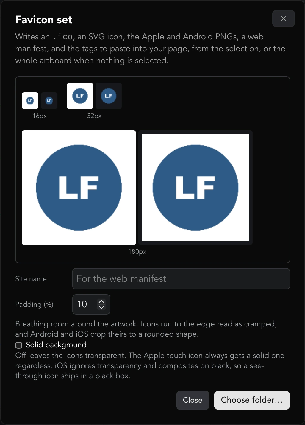
- Site name is written into the web manifest.
- Padding (%) adds breathing room around the artwork, 10% by default and up to 40%. Icons that run to the edge read as cramped, and Android and iOS crop theirs to a rounded shape.
- Solid background paints a color behind the icon; pick it with Color. Off leaves the icons transparent. The Apple touch icon always gets a solid background regardless: iOS ignores transparency and composites on black, so a see-through icon would ship in a black box.
Press Choose folder… to write the set. The dialog then lists what was written: favicon.ico (holding the 16, 32 and 48 px sizes), favicon-16x16.png, favicon-32x32.png, apple-touch-icon.png (180 px), icon-192.png, icon-512.png, favicon.svg, site.webmanifest and head.html. Paste the contents of head.html into your page's <head>.
Printing: opening the Print dialog
Click Print in the top bar, or press ⌘P (Ctrl+P on Windows). The browser's own print path cannot see the canvas, so LineaForge always opens its own dialog and drives the printer natively.
What gets printed depends on the selection: with nothing selected the dialog says Print the whole artboard.; with objects selected it says Print the selected objects. A selection is printed where it sits on the artboard, not moved to the corner, so the rest of the page simply comes out empty.
The artwork is printed on the artboard color, or on white when the artboard is transparent, and it is rendered at about 192 dpi.
Printer, paper and driver options
- Printer lists the printers your computer knows about, with the system default first. On macOS a printer that has been found on the network but not added to the computer is listed with (not set up) after its name; nothing is known about its paper or margins, so add it in your system's printer settings to get a real preview.
- Paper lists the media sizes the selected printer offers, each with its real printable area. It starts on the paper the printer queue is currently set to, and your choice is remembered.
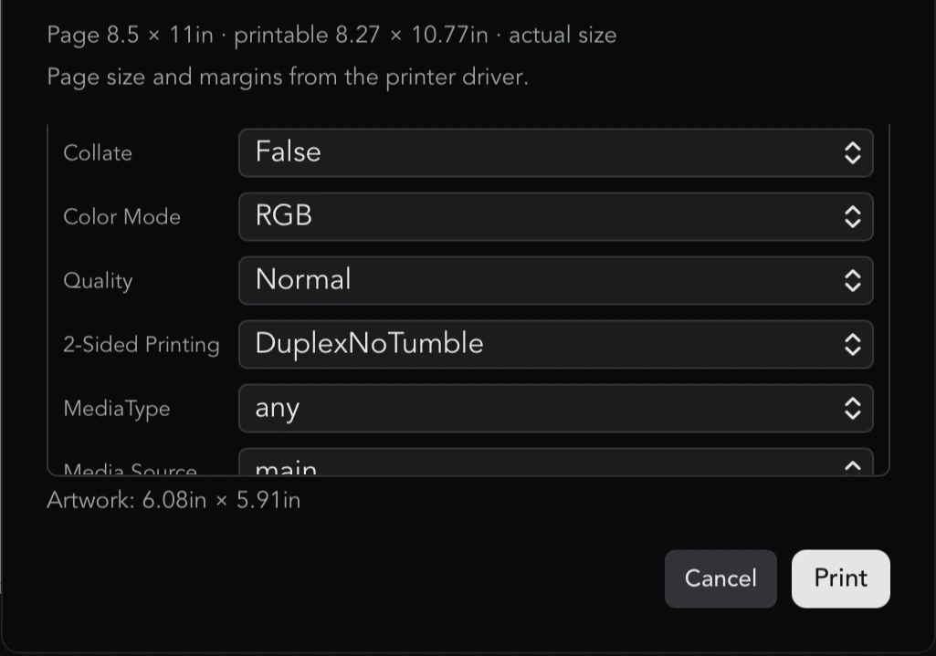
- Any other options the driver exposes (tray, duplex, quality, color mode, and so on) appear as extra dropdowns below Copies, each starting on the driver's default. Only options with more than one choice are shown.
Orientation, scale and copies
- Orientation is Portrait or Landscape. It is sent to the printer as well as drawn, so the preview and the print cannot disagree.
- Scale is Fit to page or Actual size. Fit to page scales the whole page to fill the printable area, keeping its proportions and centering it. Actual size prints at true physical dimensions, anchored at the top-left of the sheet, so a 100 mm object measures 100 mm on paper; on macOS it goes out as a PDF with the real page size so the print system cannot quietly rescale it.
- Copies is how many to print.
Reading the print preview
The preview draws the sheet to scale: the paper, a dashed rectangle for the printable area, and the artwork exactly where the printer will put it. Anything hanging off the sheet is clipped, because that is what really happens. On borderless media the dashed rectangle is left out, since the printable area is the whole sheet.
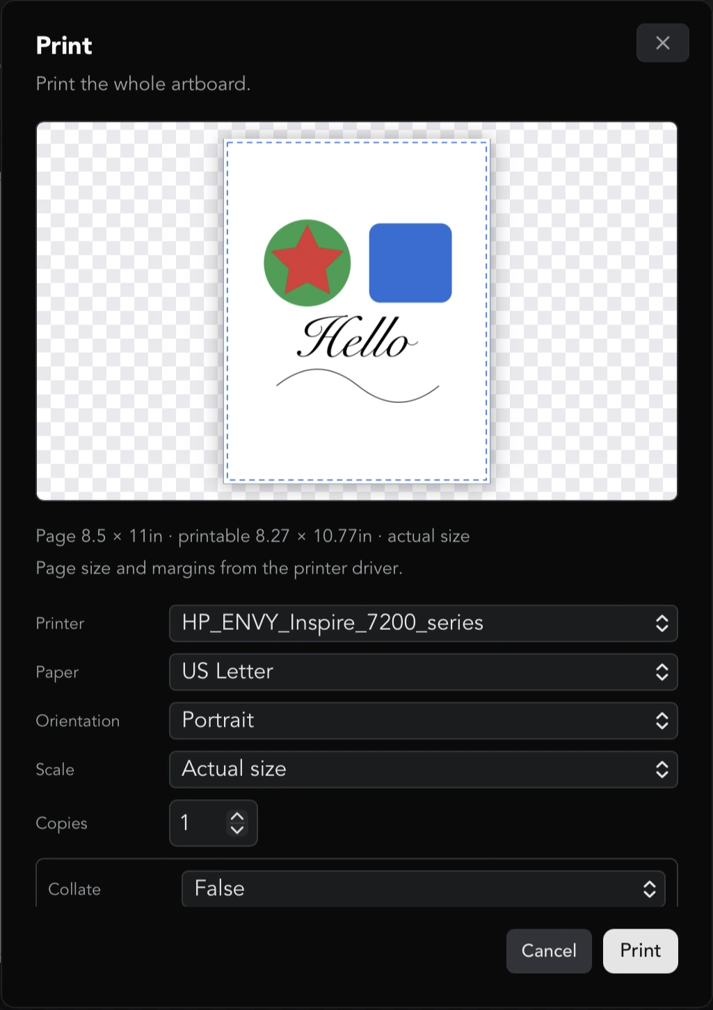
Under the preview a line reports the facts: the page size, the printable area (or borderless), and either actual size or scaled to N%. A second line says where that geometry came from: the printer driver, the printer itself or the printer description file. Further down, Artwork: gives the inked size of what you are printing, and the size it occupies on the artboard when the two differ.
If part of what you have drawn falls outside the printable area, a red warning says how far and that it will be cut off: choose a larger paper, or switch to Fit to page. The warning measures ink, not paper, so an artboard that is the size of the page does not trigger it on its own.
When no page geometry is available the artwork is shown on its own, without a page outline, rather than drawn inside a guess.
Press Print to send the job. Press Cancel to close without printing.
Platform notes for printing
On macOS, LineaForge reads paper sizes and margins from the same source the system print panel uses, which is the only source that knows about borderless media; the printer description file is a fallback for older queues, and a driverless queue with no description file still gets a preview from the printer itself. The default printer is whatever the system has set. The printer list includes printers merely discovered on the network, marked (not set up).
On Windows, printers are the ones added to Windows, local or connected, and each paper's size and unprintable border are asked of the printer driver directly. Driver options such as paper, tray, duplex, resolution and color are the ones the driver reports. There is no "discovered but not set up" category on Windows: if a printer is listed, it can be used.
Whichever platform you are on, the preview is computed by the same code that prints, from the same data, so what you see is what the printer is told.
Registration marks in the Plotter dialog
Print-and-cut needs registration marks: four L-shaped marks around the design that the cutter's camera reads to align the cut to the print. They are set up where the job is: click Plot, and on the Output tab find Print & Cut. Whether a document is a print-and-cut job is still a property of the document, so the marks are shown on the artboard at all times and the settings are saved in the .lf file, so a print-and-cut sheet opens next time already set up.
- Registration marks (print & cut) turns them on. Everything below appears once it is ticked.
- Placement chooses what the marks surround. Around objects hugs the design's bounding box, grown by the mark offset. Relative to page pins the marks to the artboard, inset by the offset, independent of where the artwork sits.
- Mark size is L 20 × 20 mm (the default) or L 9 × 9 mm.
- Mark offset (mm) is the gap between the design and the marks (outside the objects) or between the page edge and the marks (inset from the page), depending on placement. The default is 10 mm.
- Line thickness (mm) is the stroke of the marks. The default is 1 mm.
- Origin corner is which mark you will set the cutter's origin over: Bottom-right (the default), Bottom-left, Top-right or Top-left.
The marks are only printed and previewed. The cut job never draws them: the camera reads the printed marks, and cutting through them would destroy them.
If the marks would run past the page, the section warns: Marks extend past the page. Reduce the mark offset above or the design size.
Showing printer margins on the artboard
Also in File → Document…, the Printer margins section lets you keep the printable area in view while you lay a sheet out. Pick the Printer and check Show printable margins on the artboard; a dashed inset rectangle then marks the area the printer can reach, and the dialog reports the inset on each side in millimeters. The printer is shared by every document (and by the Print dialog), because it is the hardware in the room; whether the margins are drawn is remembered with the document. For a driverless queue whose margins are not available, the dialog says so and the overlay is simply omitted.
Marker tuning (experimental)
Under the mark settings is a Marker tuning (experimental) section, collapsed until you click its heading. The Skycut camera command format is unverified on hardware, so if the cut overshoots a mark or comes out rotated, these are the knobs to try, then re-print and cut:
- Cut orientation maps the cut onto one of eight orientations relative to the printed marks: Default (Skycut C-series), No change, Rotate 90° CW, Rotate 180°, Rotate 270° CW, Mirror (swap X/Y), Mirror + 90° CW and Mirror + 270° CW. The default is the orientation confirmed on a C-series. Test it with an obviously asymmetric shape, such as a triangle or a letter F: a symmetric layout hides a wrong orientation because it maps onto itself.
- Swap width/height order (TB26 / FSIZE) swaps the two numbers in the camera commands.
- Working field (FSIZE) sends either the Mark rectangle or the Design bounds as the camera's working field.
Leave these alone unless a print-and-cut job registers wrongly.
Printing the sheet with marks
With print & cut on, the Print & Cut section shows a Print with marks… button. It opens Print & cut: print with marks, a print dialog built for this one job.
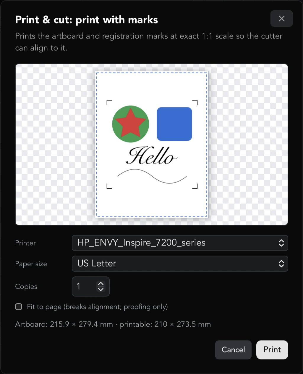
- It always prints the whole artboard, always in portrait, and always on white. The camera finds the black marks by contrast, so printing them over a colored artboard risks a failed alignment and wasted material. The sheet is rendered at 288 dpi to keep the marks crisp.
- It prints at exact 1:1 by default. Fit to page (breaks alignment; proofing only) rescales the sheet; the marks then land closer or farther apart than the cut job expects, so use it only to check a layout, never for a sheet you intend to cut.
- Printer lists only printers that are set up, since judging whether the marks fit needs real margins. Paper size lists that printer's media. Copies is how many sheets.
- The preview draws the sheet, the printable area, the artboard at 1:1 and the marks exactly where the camera will look for them. Under it, Artboard: and printable: give both sizes in millimeters.
The check that matters is whether every mark will print. If one would fall outside the printable area the dialog says so in red: reduce the mark offset in Document settings, shrink the design, or pick larger paper. Artwork running off the edge is mentioned separately and quietly, because it costs you part of the design but not the alignment: the marks still print.
Verify the first sheet with a ruler: a 20 mm mark arm must measure 20 mm, and the distance from mark corner to mark corner must equal the design's size plus twice the offset. Some drivers apply a "borderless expansion" that shifts the marks; if yours does, pick a non-borderless paper.
Print-and-cut, start to finish
- Add a machine that supports print-and-cut (Plot → Manage machines…; the Skycut C, D and V series are listed with print & cut). Select it under Machine.
- Under Print & Cut, tick Registration marks (print & cut), choose the Placement, and adjust the offset until the marks sit inside the page and, if you have Show printable margins on the artboard on in File → Document…, inside the dashed printable area.
- Mark which objects are cut lines. The contour you want cut should be set to Cut (blade), and the printed artwork underneath it to Ignore (right-click → Plot settings…), so the cutter follows only the outline. An image imported with a transparent background while Trace cut lines on imported cutouts is on in Preferences already has such an outline.
- In the same section, press Print with marks…. Check the preview for a red warning, leave Fit to page off, and press Print.
- Load the printed sheet into the cutter and set the blade origin over the mark named in Origin corner, the lower-right mark by default.
- Back in the Plotter dialog, choose the transport under Connection and press Cut. The job is sent in the cutter's camera (marker) mode: the machine scans the four marks, builds its coordinate frame from them, and cuts the contour aligned to the print. The machine rotation set in Plotter defaults is ignored for this job, since the camera reconciles the axes itself.
Print-and-cut has not yet been confirmed end to end on any machine. Put the pen tool in the cutter instead of a blade for the first run: if the pen traces the printed outline, switch to the blade; if it is offset or turned, adjust Marker tuning and try again. See the Plotting and cutting help for the cutter side of this workflow.
Troubleshooting exports
- Selection only is grayed out: nothing is selected. Select the objects first, then open File → Export.
- The exported picture has a white or colored background you did not want: Whole artboard paints the artboard color. Either check Transparent (no paper behind the artwork) under Background in File → Document…, or export with Selection only, which is always transparent around the objects.
- A JPEG has a background where the PNG was transparent: JPEG cannot hold transparency; use PNG or WebP.
- A faded object is solid in the file: you exported EPS, which has no transparency. Use SVG, PDF or a picture format.
- A placed image is missing from the PDF or EPS: both skip embedded images. Use SVG or a picture format.
- The DXF opens as plain lines with no colors: that is how DXF export works. Every object becomes a polyline on one layer; assign colors or layers in the receiving program.
- The STL is the wrong thickness: give the objects an extrude depth with the Extrude effect; objects without one use the 6 mm (0.25 in) default.
- The export failed with a message: the message names the file operation and the underlying error, usually a folder you cannot write to or a file that is open elsewhere. Pick another location and try again.
Troubleshooting prints
- No printers found: nothing is set up on this computer. Add the printer in your system's printer settings, then reopen the dialog.
- Paper says Unavailable: the printer's media list could not be read. On macOS this happens for a printer that is discovered but not set up; add it to the computer.
- The preview has no page outline: no geometry is known for this printer, so the artwork is shown alone rather than inside a guess. Printing still works, but you will not be warned about clipping.
- A print comes out the wrong size: make sure Scale is Actual size, not Fit to page, and check the driver options for anything that rescales.
- A print-and-cut sheet does not register: measure the marks first (see above). If the sizes are right, the problem is on the cutter side; see Marker tuning and the Plotting and cutting help.
- Something drawn on screen is missing from a print or image export: every effect the canvas draws (line fills, shadows, extrusions, variable-width strokes) is rendered by the same code when printing and exporting pictures. EPS drops opacity, and PDF and EPS skip embedded images; use SVG or a picture format for those.