
Objects, color and layers
Every object on the canvas has a size, an outline, a fill, a color, a place in the stacking order, and a job to do when the design reaches the machine. This page covers the three places those live: the Inspector on the right, the color controls on the left tool rail, and the Objects panel.
The Inspector at a glance
The Inspector is the panel on the right headed Inspector. With nothing selected it says No selection. Select one object and its name appears at the top; select several and it reads, for example, 3 objects. Most edits in the Inspector apply to every selected object at once.
The sections, from the top: Align (only with two or more objects selected), Dimensions, Polygon, Star or Arrow (only while the shape is still a live polygon, star or arrow), Opacity, Line, Effects (collapsed by default), Scene view (only when 3D is enabled), and a Delete button at the bottom.
Fill and stroke colors are deliberately not in the Inspector. They live in the color widget at the bottom of the tool rail, described under "Fill and stroke swatches on the tool rail" below.
Editing several objects at once
With a multi-selection the Inspector shows the values of the primary object (the one clicked first) and applies each change to every selected object. A few details worth knowing:
- Dimensions shows the combined size of the whole selection, and resizing scales the group as one block.
- Opacity shows the primary object's value rather than an average, and sets every selected object to the value you choose.
- Giving a line fill, shadow or extrusion to a selection adds it to every object that lacks one. Changing one setting, such as the shading on an extrusion, keeps each object's other settings, so objects with different depths keep their depths.
- Stroke width and dash edits apply to every selected object that has an outline.
Size and proportions
The Dimensions section shows the selection's Width and Height in the current unit, which appears in the heading, for example Dimensions (mm). Type a new value and press Enter or click away to resize. The selection is anchored at its top-left corner, so a multi-selection keeps its relative layout and simply scales as a block.
Constrain proportions is checked by default: changing the width scales the height to match, and the other way round. Untick it to stretch one axis on its own.
Moving, rotating and resizing on the canvas
There are no X, Y or rotation fields in the Inspector. Position and angle are set on the canvas with the Select tool (S).
- Drag an object to move it. Hold Shift to keep the move straight along one axis. Hold Alt/Option (⌥) while dragging to pull off a copy and leave the original where it was.
- Press the arrow keys to nudge the selection by 1 mm (1/16 in). Hold Shift for a finer step of 0.1 mm (1/64 in).
- Drag a corner handle to resize. Corners keep the proportions by default; hold Ctrl to release that constraint. An edge handle resizes along one axis and never needs a modifier.
- The round handle at the top-right of the selection box rotates the selection about its center. Hold Shift to snap the angle to 15 degree steps.
Aligning several objects
Select two or more objects and an Align section appears with seven buttons: Align left, Align center, Align right, Align top, Align middle, Align bottom, and, set slightly apart, Center on both axes. Each lines the objects up against the combined bounds of the whole selection.
Polygon and star corners
While a polygon or star is still a live shape, a Polygon or Star section offers its corner count: Sides for a polygon, Points for a star, plus Inner (%) for a star, which is how far the inner points cut in. The section disappears once the geometry has been edited into a plain path (a node edit, a boolean, a simplify), because from then on the count is no longer something the object has.
While an arrow is still a live shape, an Arrow section offers its Length, Shaft width, Head length, Head width and Sweep (°), in the document's unit. The same dimensions can be dragged on the canvas; see Drawing tools. It disappears for the same reason the Polygon and Star sections do.
With the Edit nodes tool (N) and a corner node selected, a Corner section lets you type a size and click Round to round that one corner with that radius, or Chamfer to cut straight across it that far back along each edge.
Opacity
The Opacity section has a slider and a number field in percent. It fades everything the object draws together: fill, outline, line fill, shadow, and an imported picture. Dragging the slider is one undo step for the whole sweep.
Fading is not hiding. An object at 0% is still there: still selectable, still listed in the Objects panel, and still cut or drawn. Opacity describes how artwork looks on screen; the machine follows the outline either way. To take something out of a job, hide it with the eye icon in the Objects panel.
Stroke width, alignment and dash pattern
The Line section describes the outline's shape rather than its color. If the object has no outline it simply says No stroke. Give it one by picking a stroke color in the tool rail's color widget.
- Width is the outline's thickness, set with the slider or the field beside it. Neither has a unit: the value is in document pixel units (96 per inch), not mm or inches, so 0.25 is a fine hairline, 1 is a thin line and 4 is a bold line. New shapes, pen paths and the weed box start at 0.25, and the arrows on the field step by 0.25. The slider runs to 24; the field takes any width, and a larger one parks the slider at its end. Dragging the slider is one undo step for the whole sweep.
- Align chooses which side of the edge the width sits on. Center straddles the edge, half in and half out, which is how every outline used to be drawn. Inside keeps the whole width within the shape, for a border inside a sticker that must not change its cut size. Outside puts the whole width beyond the edge, for a halo around artwork. Only a closed shape has an inside, so an open path is drawn down the middle whichever is chosen, and a shape narrower than an inside stroke has nowhere to put the line and shows none. The machine follows the line where it is drawn: an inside or outside stroke is cut or drawn along the moved line, not the original edge. The alignment applies to the whole selection, like the width, and has no effect while a stroke profile is active.
- Dash shows the current pattern, either Solid or the step lengths in the current unit, with an Edit… button that opens the Dash pattern dialog.
- Reset stroke profile appears only when the outline has been given a variable width with the Stroke Profile tool (W), and returns it to a uniform width.
Line caps and joins are stored with the stroke but have no controls in this version.
The Dash pattern dialog
The Dash pattern dialog builds a dash and gap rhythm step by step, with a live preview along the top at the pattern's true proportions and the canvas updating as you edit.
- Click a preset to start from it: Solid, Dashed, Dotted, Dash-dot, Long dash or Short-long. Presets are defined in millimeters, so they mean the same thing in either unit.
- Steps alternate between dash and gap and are labeled Dash 1, Gap 1, Dash 2 and so on, in the current unit. Click Add step for another and the X button beside a step to remove it. Clear empties the list, which is a solid line.
- An odd number of steps repeats to an even one, and the dialog says how it will read.
- Apply (or Enter) keeps the pattern as a single undo step. Cancel, Escape, or clicking outside puts every object back exactly as it was.
Line fills: hatching, crosshatch, wave and cells
A line fill is the set of lines a pen or engraver draws inside a shape, as opposed to a flat fill color, which a pen cannot draw. It lives in the Effects section under the Fill tab. The Effects section starts collapsed; click its heading to open it. A small dot on the heading, or on a tab, means that effect is switched on.
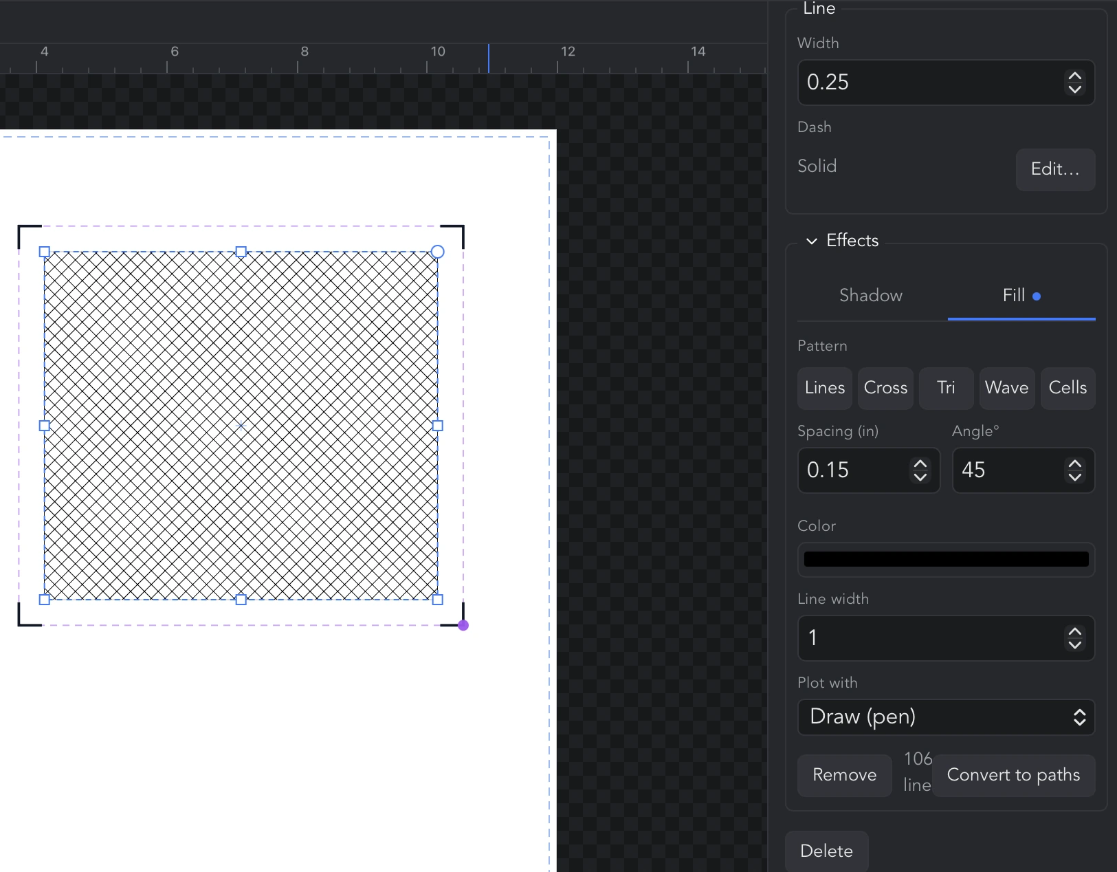
Clicking the Fill tab on an object without a fill gives it one straight away (or click Fill with lines). The controls:
- Pattern: Lines (parallel lines in one direction), Cross (two sets at right angles), Tri (three sets, sixty degrees apart), Wave (parallel sine curves, for a softer texture) and Cells (a Voronoi cell network, with its own settings below).
- Spacing is the gap between neighboring lines, in the current unit, and Angle° is their direction (0 is horizontal, 90 vertical). Both are hidden for the Cells pattern.
- Color and Line width are the fill's own, independent of the object's outline. A new fill starts in the object's stroke or fill color so the first result is visible.
- Plot with decides what the machine does with the fill: Draw (pen), Cut (blade) or Skip when plotting. This is separate from the object's own role, which is what lets one shape be cut round the edge and drawn on the inside.
- Head appears only when the active machine has more than one tool carriage. Automatic (by role) sends drawn work to the pen head and cuts to the blade head; naming a head overrides that without changing the role.
- The count at the bottom, for example 240 lines, is how many separate pen-down moves the fill comes to. Spacing is where a slipped decimal point is otherwise invisible until the plotter is halfway through, so check this number.
- Remove takes the fill off. Convert to paths turns it into real geometry, selected and ready to edit or cut like anything else.
Spacing is stored as a physical size, so scaling the artwork afterwards does not change the gap between lines.
Viewing fills on the canvas
Two buttons on the top bar change how fills look on screen without changing the artwork. Toggle fills switches between the normal view and an outlines-only cut-line view; its tooltip reads Hide fills: show outlines only (cut-line view) or Show fills. Toggle loose-end markers shows or hides the dots that mark where open paths end, which is useful because a line fill has hundreds of ends on purpose and the dots can bury the artwork.
Cut the outline, draw the inside
The most common use of a line fill on a vinyl cutter with a pen holder, or a plotter with two heads:
- Draw or select the shape. Its own plot role is Cut (blade) by default, so the outline will be cut.
- Open Effects, click the Fill tab, and choose a pattern, spacing and angle.
- Leave Plot with on Draw (pen). The fill is drawn and the edge is cut, in one job on a two-head machine or with a prompt to change tools on a single-head one.
- Check the line count at the bottom of the tab before sending a large job.
Cells (Voronoi) settings
With the Cells pattern the fill is a network of irregular cells, and these controls replace spacing and angle:
- Draw: Cell edges draws the boundaries between cells; Center lines draws straight lines joining neighboring cell centers instead.
- Cells is how many cells to aim for. Relax is the number of relaxation passes: none looks random, a few look considered (up to 20).
- Arrangement is a seed number. The same number always gives the same cells, so an arrangement worth keeping can be saved and returned to. The dice button, Try another arrangement, rolls a new one.
- Min is how close two cell centers may sit, which stops slivers. Max splits cells wider than this; zero leaves them unbounded.
- Round and Gap (only for Cell edges) round each cell into its own tile and pull it in from its neighbors. Both mean every shared edge is drawn twice, so the plot takes about twice as long.
- Cut cells at the edge clips the network to the shape's outline.
Cut, draw or ignore: an object's plot role
Every object has a plot role that tells the machine what to do with its outline. The default is to cut it. To change it, right-click the object on the canvas and choose Plot settings…, or click the scissors badge on its row in the Objects panel. The Plot settings dialog applies to the whole selection, or to every member of a group when opened from a group row.
- Role: Cut (blade), Draw (pen) or Ignore. Ignore skips the object when plotting while leaving it in the design. With a mixed selection the field shows Mixed and leaves each object's role alone unless you change it.
- Head appears only on a machine with two carriages: Automatic (by role) or a named head. Naming a head keeps the role, so a cut stays a cut, with blade offset and overcut, whichever head runs it.
- Force, Cut speed and Passes are optional overrides. Blank fields use the plotter defaults. More than one pass cuts the same outline again, for material too dense or thick to get through in one go, up to 10.
- Reset to defaults clears every override; Apply keeps them.
Once an object is anything other than a plain default cut, a scissors badge appears on its row in the Objects panel. Point at the badge to read the settings, for example Plot: draw · 3 passes (edit), and click it to reopen the dialog. The role is independent of the stroke color: a drawn object's stroke color decides which pen it uses, as described under "Why color matters for plotting".
Shadow effect
The Shadow tab of the Effects section adds a derived copy behind the object. Clicking the tab adds one (or click Add a shadow). Type is Drop (a copy offset behind the shape), 3D (offset and filled in between, so it reads as a solid slab) or Cast (anchored at the foot of the shape and leaned over, as if lit low). Color and Opacity set its paint, Expand grows it and Round softens its corners, both in the current unit. The shadow's shape is dragged on the canvas: with the object selected, drag the shadow handle. Remove deletes it; Convert to paths turns it into a real, cuttable object, welded into one piece.
3D extrude and the scene view
3D is experimental and off by default. It has nothing to do with cutting: what the machine follows is always the flat outline. To switch it on, open Preferences and tick Enable 3D (Experimental). That adds three things: a 3D button on the top bar, the Orbit (drag to turn the scene) tool (V) on the tool rail, and a 3D tab in the Inspector's Effects section.
To give a shape depth:
- Select it, open Effects and click the 3D tab.
- Tick Extrude into 3D. The first extrusion turns the scene to an isometric view automatically, since straight on an extrusion hides behind its own face.
- Set Depth in the current unit and choose whether to Shade faces by their angle to the light.
The Scene view section controls the camera for the whole drawing: Tilt° and Turn° fields, the presets Front, Isometric and Dimetric, and Pivot on selection or Pivot on all to choose what the scene turns around. The Orbit tool turns the same camera by dragging. The 3D button on the top bar switches between the projected view and the flat artwork.
Convert to paths replaces an extruded object with its projected faces as real paths, which is how a 3D look gets cut or drawn. Turning 3D off in Preferences flattens everything on screen, but the depth stays on each object and comes back when it is turned on again. STL export is covered elsewhere.
Deleting an object
The Delete button at the bottom of the Inspector removes the selected object, as do the Delete and Backspace keys on the canvas and the trash icon on the object's row in the Objects panel.
Text and image objects
A text object gets its own panel for font, size, spacing and alignment, and an imported picture gets crop and trace tools; both are documented on their own pages. Everything on this page still applies to them: text and images have an opacity, a place in the Objects panel and a plot role, and converted text takes line fills like any other shape.
Fill and stroke swatches on the tool rail
At the bottom of the left tool rail sit two overlapping swatches: the stroke frame behind and the fill square in front. Each shows its color, or a slash for none. With an object selected they show that object's paint; with nothing selected they show the defaults that every newly drawn shape receives, and those defaults are remembered between sessions.
- Click the fill swatch (Fill: #ff0000 (click to edit)) or the stroke swatch (Stroke: none (click to edit)) to open the Color Chooser for that paint.
- Swap fill and stroke exchanges the two. With objects selected, each one trades its own fill color for its own stroke color, so a selection in several colors keeps them all; a stroke keeps its width and dash pattern. A shape with only a fill becomes an outline in that color, and one with only an outline becomes filled. Afterwards the defaults match what the swatches show, as they do after picking a color. With nothing selected, it swaps the defaults.
- The small button labeled Set fill to none or Set stroke to none, depending on which paint is active, removes that paint from the selection and from the defaults.
Picking a color anywhere, whether in the Color Chooser, the palette bar or the Eyedropper, recolors the current selection and becomes the default for new shapes.
The Color Chooser
The Color Chooser is a small window that opens from either swatch and can be dragged anywhere by its title bar. At the top, Fill and Stroke choose which paint you are editing, beside a preview of the current color.
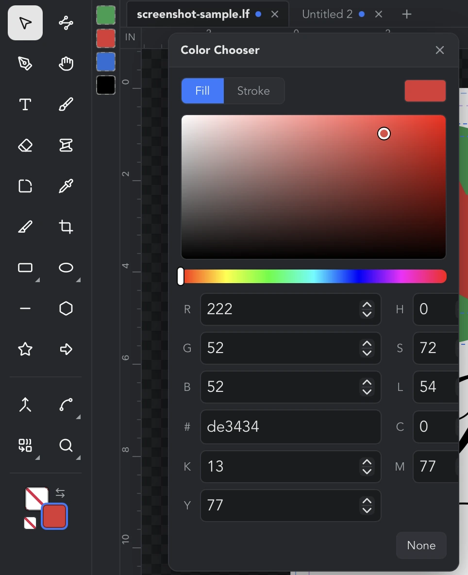
- Drag in the large square to set saturation and brightness, and along the strip beneath it to set the hue. The canvas updates live while you drag; releasing commits one undo step.
- The fields set the same color by number: R, G, B (0 to 255), H, S, L (hue 0 to 360, the rest 0 to 100), # for a hex code, and C, M, Y, K (0 to 100). They all describe one color, so changing any of them updates the rest.
- Pick samples a color from anywhere on the screen, including outside the app. It appears only when the system supports it.
- None removes the paint entirely: a fill of none is an outline-only shape, a stroke of none has no outline.
- Close the window with its X or by pressing Escape.
The palette bar: every color in your document
A thin strip of swatches beside the tool rail, labeled Document colors, lists every color the artwork uses. It is a reading of the document rather than a palette you curate: a color appears when something is painted with it and disappears when the last object using it is deleted or recolored, and there is nothing to add or remove by hand. Swatches stay in the order the colors first appeared, so none moves out from under your cursor as you work. The swatch matching the current fill or stroke color (whichever is active in the Color Chooser) is marked as current.
- Point at a swatch to read its hex value and what it is doing, for example #ff0000 · 3 fills, 1 stroke.
- Click a swatch to make it the current color, which recolors the selection if you have one.
- Right-click a swatch (Ctrl+click on a Mac) to select every object using that color. This is what the strip is really for: "show me everything that goes on the red sheet" in one action. Hidden and locked objects are left out, and a swatch whose objects are all hidden or locked selects nothing rather than reaching past the eye and padlock icons.
Three things worth expecting. Fills and outlines count, but a line fill's color does not appear on its own. The same color at two different opacities is two swatches, because they are two different paints and they cut as two. And an empty strip simply means nothing on the canvas has a fill or stroke yet.
The Eyedropper tool
The Eyedropper (copy fill & stroke) tool (I) copies paint from one object onto others. The order matters: select the objects to restyle first, then switch to the Eyedropper and click the object to copy from. The hint under the canvas says which step you are on. It copies the fill color, the stroke color and the stroke width, including any transparency, and nothing else: geometry, opacity and a variable-width stroke profile on the source are left alone. The tool stays active afterwards, so several objects can be restyled in a row.
This is different from the Pick button in the Color Chooser, which samples a single screen pixel from anywhere on the display.
Color formats
Colors are stored as hex. The Color Chooser's # field accepts a three-digit (#f00) or six-digit (#ff0000) code, with or without the leading #. The palette bar and swatch tooltips show six digits for an opaque color and eight (#rrggbbaa) for a translucent one. There are no named colors in the app's own fields, but an imported SVG may use a few keywords: black, white, red, green, blue, currentColor, and none or transparent for no paint. Any other color name in an SVG is read as black.
Why color matters for plotting
On a pen plotter, color is how the app knows which pen to use. With Prompt for tool change ticked on the Plotter dialog's Output tab (shown only for single-head machines), a job runs one tool at a time: every cut object is the blade, and every drawn object is a pen in its stroke color. A design with black lines, red lines and a cut outline is three tools. Between tools the material feeds forward, the head moves aside, and the app waits with a prompt saying which tool to load.
Two practical consequences:
- Give lines that should share a pen exactly the same stroke color. Two slightly different reds, or the same red at two opacities, are two pens. Right-click a swatch in the palette bar to check what a color is used by.
- The tools come in the order they first appear reading the Objects panel from the top, so arrange the list to set the pen order.
On a machine with two heads, cuts go to the blade head and drawn work to the pen head in a single job, and the Head control in Plot settings or on a line fill can override that per object.
Give each pen its own color
- Select everything that should be drawn with one pen. Right-click a swatch in the palette bar to grab every object already in that color, or Shift+click rows in the Objects panel.
- Click the stroke swatch on the tool rail and pick the color in the Color Chooser, or click a swatch in the palette bar. Repeat for each pen.
- Right-click the selection, choose Plot settings…, set Role to Draw (pen) and click Apply. A scissors badge appears on each row in the Objects panel.
- Arrange the Objects panel so the first object of each color sits in the order you want to load the pens.
- In the Plotter dialog, tick Prompt for tool change on the Output tab. The Cut preview beside it lists the tool order before you send.
The Objects panel
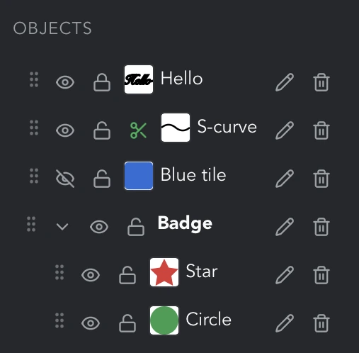
The Objects panel lists everything on the canvas, topmost first, so the row at the top is the object in front. An empty canvas shows Canvas is empty. Each row has a drag grip, an eye, a padlock, a small thumbnail of the object's geometry, its name, a pencil, and a trash icon, plus a scissors badge when the object carries plot settings. A group is a row with a chevron, and its members are listed indented beneath it.
What the icons mean
- Grip (Drag to reorder): press and drag to move the row.
- Eye (Hide / Show): whether the object is drawn on the canvas and included in a job.
- Padlock (Lock / Unlock): whether the object can be selected on the canvas.
- Scissors (Plot: cut · 2 passes (edit)): the object has plot settings other than a plain cut; click to edit them. On a group row it reads Plot settings set on group members (edit) and opens the dialog for every member.
- Pencil (Rename): rename the row.
- Trash: Delete on an object row; Ungroup on a group row, which dissolves the group and keeps its members.
- Chevron (Expand / Collapse): fold a group's members away.
Selecting from the list
Click a row to select that object; it is highlighted in the list and on the canvas. Click a group row to select every member of the group. Shift+click adds a row to the selection or takes it out again, the same as Shift+click on the canvas, so several objects can be picked out of the list and worked on together. Shift+clicking a group takes all of its members; Shift+clicking it again puts them back. A row can be selected even when the object is locked, which is the way to get at a locked object without unlocking it.
Reordering by drag
Press on a row and drag it up or down. A line shows where it will land, above or below the row under the pointer. The stacking order on the canvas follows the list: higher in the list is in front.
- Drag an object among another group's members to move it into that group, or drag it out onto a top-level row to take it out of the group.
- Drag a group row to move the whole group. Groups cannot be placed inside other groups.
The same moves are available from the canvas: right-click an object and open Arrange for To top, Move up, Move down and To bottom.
Show, hide and lock
Click the eye to hide an object. A hidden object is not drawn, cannot be selected on the canvas or by Select all, and is left out of every job, which makes hiding the way to take something out of a cut without deleting it. Click the eye again to show it.
Click the padlock to lock an object. A locked object stays visible and is still cut or drawn; locking only stops a sweeping drag, a nudge or a Delete on the canvas from picking it up. Select all skips locked objects too. Hiding or locking a group row applies to the whole group.
Renaming objects and groups
Double-click a name, or click the pencil on its row, to edit it in place. Press Enter to keep the new name, Escape to abandon the edit. A blank or unchanged name is discarded. Names appear at the top of the Inspector and are a convenient way to tell pieces apart in a long list.
Grouping and ungrouping
Select two or more objects, right-click one of them on the canvas and choose Group selection. The new group appears in the Objects panel as a row named Group with the members beneath it, and the whole group is selected. Clicking any member on the canvas selects the group. To dissolve a group, right-click a member and choose Ungroup, or click the trash icon on the group row. Groups are one level deep: a group cannot contain another group. Some generated artwork arrives already grouped, for example each layer of a Vexel pattern from the Image Path dialog, so a layer can be hidden, locked, reordered or given its own pen as a unit.
How the order affects plotting
An ordinary job follows the document order, starting at the bottom of the Objects panel and working up, so the piece listed last is cut first. With Prompt for tool change on, the job walks the panel from the top instead, because that is the order the tools are listed in and the one you arranged the panel to get; the objects within each tool keep that order too. Travel optimization, when on, reorders within a tool rather than across the whole job. Hidden objects and objects whose role is Ignore are never sent.
Shortcuts on this page
- S: Select tool, for moving, resizing and rotating.
- N: Edit nodes tool, which also enables the Corner section.
- I: Eyedropper, to copy fill and stroke onto the selection.
- W: Stroke Profile, for a variable-width outline.
- V: Orbit, to turn the 3D scene (only with 3D enabled).
- Arrow keys nudge the selection; Shift for the finer step.
- A corner handle keeps proportions on its own (Shift asks for the same); Ctrl+drag releases them; Shift while rotating snaps to 15 degree steps.
- Shift+click adds to or removes from the selection, on the canvas and in the Objects panel.
- Delete or Backspace removes the selection.
- Cmd/Ctrl+A selects everything visible and unlocked.
- Escape closes the Color Chooser and cancels an in-progress rename.